
medieval watermills technology turned flowing water into steady mechanical power and reshaped production across the preindustrial world.
A wheel captured the push of water and spun a shaft that drove stones, saws, hammers, or rollers. This simple transfer of motion made grinding grain and shaping timber more reliable than hand tools. Early engineers from the Greek and Roman centuries recorded gears and wheels that set the way for later development.
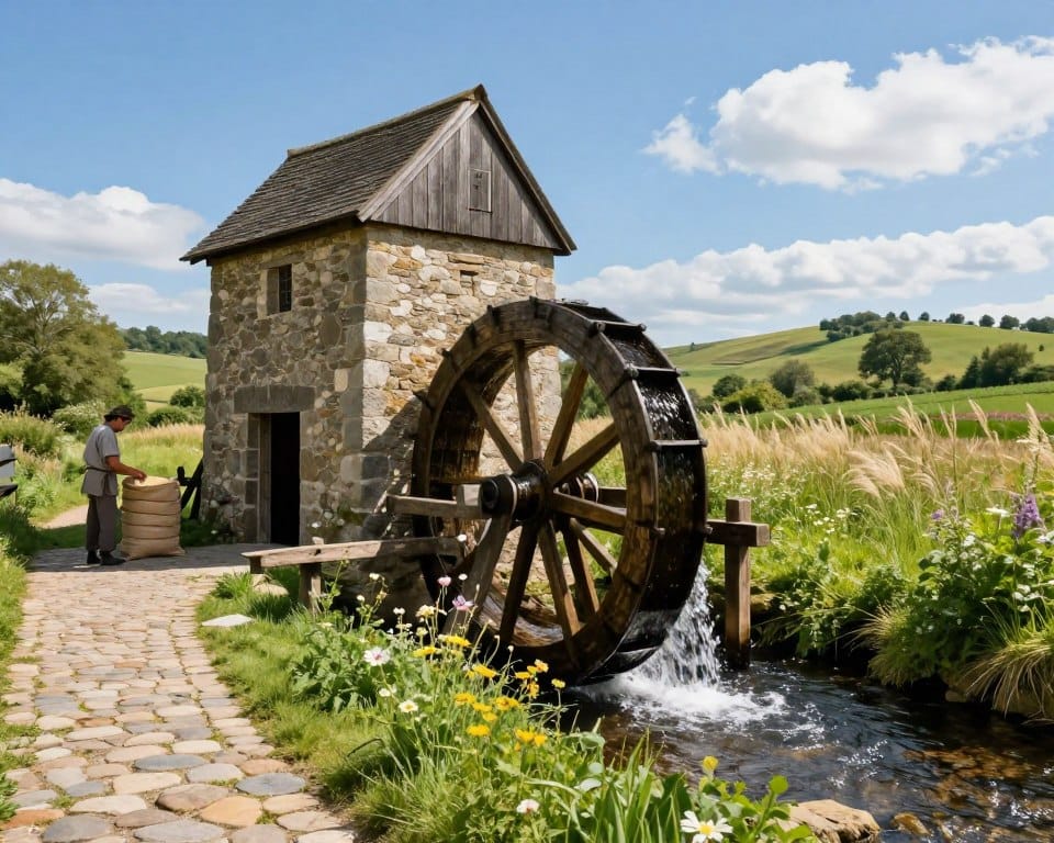
Different layouts matched local flow. Undershot wheels used fast current. Overshot wheels used a drop and stored energy. Horizontal wheels removed gearing in some water mill designs.
Readers will learn how leats, gears, and wheel arrangements created repeatable processes. The result was higher output and steadier quality at many mills. Understanding these parts helps decode archaeological remains and historical records.
Key Takeaways
- Flowing water converted to rotary motion powered diverse milling and manufacturing tasks.
- Wheel orientation and gearwork determined how much usable power a site could deliver.
- Designs evolved from Greek and Roman roots into scalable systems across the medieval world.
- Standardized, repeatable motion raised production and consistency in food and materials.
- Siting and flow control governed efficiency and the useful life of a mill.
Why watermills mattered in the Middle Ages
Rivers became engines of local economies when mills applied steady force to common tasks. In the Middle Ages this change cut labor hours and boosted the rural economy.
Shifting repetitive grinding to water saved time. A single mill handled many sacks of grain. That steady milling eased seasonal labor peaks and made flour supply more reliable.
Mills stood as fixed assets on a river. Lords and monasteries recorded them in charters and rents. The Domesday Book lists 5,624 mills in 1086, rising to perhaps 10,000–15,000 by 1300. More mills meant steadier schedules and better access to milling services.
Communities dug leats and managed sluices to use water year-round. Millers cleared sediment behind small dams and controlled flow to limit floods. These practices kept mill use consistent and raised the quality of output.
Beyond grain, mills powered fulling, sawing, and other tasks. Over time mills lowered marginal costs, encouraged specialization, and became key infrastructure projects for local prosperity.
From ancient ingenuity to medieval mastery
Ancient engineers laid the groundwork that turned river flow into organized mechanical work across centuries.
Classical foundations: Greek waterwheels and Roman engineering
Early texts record the first steps. Philo of Byzantium in the 3rd century BC described water-driven devices. Vitruvius (around 40–10 BC) gives a clear undershot wheel with gearing. Antipater and Strabo note overshot examples near Anatolia. Pliny records trip hammers by about 70 AD.
These sources show that undershot, overshot, and breastshot variants were known. The Romans systemized designs into repeatable plans. That allowed mills to run many millstones for steady grinding.
Roman power centers: Barbegal and multi-mill complexes
Large Roman projects make the point. Barbegal in Gaul fed 16 overshot wheels in cascade. It could yield roughly 4.5 tons of flour per day. The Hierapolis sawmill (3rd century AD) introduced a crank and connecting rod for reciprocal cutting.
Turbine-like wheels appear at Chemtou and Testour by the late 3rd or early 4th century. Archaeology shows a 2nd–3rd century peak in sites. Modern study explains gaps in texts as survival bias, not absence of mills.
Roman forms — geared vertical wheels and simpler horizontal wheels — set templates. They resurfaced in the medieval period where water, materials, and social organization supported mill projects. Estates then integrated mills to process grain and stabilize supply, continuing a long line of innovation.
The core mechanics: how water became mechanical power
Engineered channels and gates turned moving water into reliable rotary drive for industrial tasks. Simple civil works set head and flow so a wheel delivered steady power to a mill.

Capturing flow: leats, races, flumes, and sluices
Leats or head races divert stream water to a flume. Narrowing the flume increases velocity at the wheel. Sluice gates meter that flow and allow a mill to shut down for repairs or to survive floods.
Wheels and turbines: converting flow into rotation
Horizontal wheels drive a millstone shaft directly and need no gearing. Vertical wheels turn an axle that must be geared down or up for useful speed. Wheel type changes torque and efficiency.
Shafts, gears, and the gear train
In vertical setups the pit wheel meshes with the wallower on a vertical shaft. That shaft turns the great spur wheel. Stone nuts take speed from the spur wheel to spin the stones.
Controlling output: sluices, seasonal flow, and maintenance
Overshot wheels are roughly 2.5 times more efficient than undershot where head exists. Undershot wheels suit shallow, fast channels. Millers adjusted sluices and used tentering to hold the grinding gap and stabilize flour grade.
- Preventive maintenance on bearings, paddles, and gates reduces downtime.
- Parallel races can feed multiple wheels so work continues during service.
- Design choices respond to rainfall, sediment, and bank stability to keep performance predictable.
Types of waterwheels and layouts you’ll see on medieval sites
Choosing the right wheel depends on head, flow, debris, and local repair skill at a site. Simple layouts favor low build cost. Complex setups deliver steadier torque for heavy use.
Undershot wheels: simple setups for swift, shallow rivers
Undershot wheels suit broad, fast channels. They need little civil work. Paddles push against current. Parts wear faster and efficiency is lower.
Overshot wheels: higher head, greater efficiency for milling grain
Overshot wheels use a drop from a pond or leat. Buckets fill and deliver steady torque. They work best near hills and deliver higher efficiency with lower flow.
Breastshot and pitchback: versatile mid-head solutions
Breastshot and pitchback wheels balance build effort and performance. They handle debris better than undershot and need moderate head. Many valley examples mix these to match tributaries.
Horizontal vs. vertical wheels: when simplicity beats gearing
Horizontal wheels skip gearing and cut cost. They limit stone size and speed. Vertical wheels fit gears and drive multiple parts for larger mills.
| Type | Ideal Head/Flow | Advantages | Maintenance Notes |
|---|---|---|---|
| Undershot | Low head, fast flow | Cheap, quick install | Paddles erode faster |
| Overshot | High head, low flow | High torque, efficient | Buckets need tight joinery |
| Breastshot / Pitchback | Mid head | Good debris handling | Moderate upkeep |
| Horizontal | Variable, low construction | Simple, low cost | Limits stone diameter |
Layout factors guide choice: available head, seasonal changes, debris load, bank stability, and ease of flume construction. Local timber and stone skills change life-cycle costs. For practical guidance on origins and design, see who invented the water wheel.
Inside the mill: stones, gears, and the flow of grain
A mill’s heart is a compact chain of shafts and stones that guides grain from hopper to sack. Inside, a clear sequence of parts turns steady water into measured grinding and graded flour.
The gear train: pit wheel, wallower, and great spur wheel
The pit wheel on the horizontal shaft meshes with the wallower on the upright shaft. The upright shaft turns the great spur wheel. Pegs on the spur wheel drive stone nuts that spin the runner stones.
Millstones and tentering: setting the gap for flour grades
The runner stone turns on top of the stationary bedstone. Furrows and dressing patterns cut and shear grain. Sharp lands avoid overheating and keep the grind clean.
Tentering adjusts the gap between stones. It controls flour fineness, throughput, and stone wear. Millers change tentering as power or feed rate varies.
Throughput and scaling: one wheel, several stones
A single waterwheel can power multiple stones if the great spur wheel drives several stone nuts. By the 19th century a well-fed wheel often ran three or four stones.
- Grain flows from hopper to shoe to the eye of the stone; feed rate prevents choke or scorch.
- Sieving sorts flour and returns coarse stock for a second pass.
- Routine maintenance: dress stones, oil bearings, check gear teeth, and clear dust.
| Component | Role | Material notes |
|---|---|---|
| Pit wheel / wallower | Transmit water power to upright shaft | Hard wood or iron for durability |
| Great spur wheel | Drive multiple stone nuts | Robust joins reduce noise |
| Stones | Grind grain to flour | Stone types affect wear and grit |
medieval watermills technology in action across Europe
Legal rolls and monastic inventories reveal how resilient milling networks supported estates across centuries.
Carolingian charters and polyptychs repeatedly record rights to a mill or to a race. Studies show roughly 75% of monasteries had easy access to a mill. That figure highlights institutional priority for reliable grain processing in the early medieval period.
English records offer hard counts. The Domesday survey lists 5,624 watermills in 1086. Modern reassessment raises that number to at least 6,082. By 1300 estimates reach 10,000–15,000. These totals show rapid expansion across two centuries.
- Charters often name water access, sluices, and races, showing legal control over flow.
- Many sites hosted multiple mills or stages as demand and investment grew over years.
- Regional density varies with river networks, settlement patterns, and available head.
Interpreting the evidence
The documentary surge partly reflects better records, not sudden invention. Archaeology and research must be read together. That combined view explains continuity and supports practical lessons on siting, head control, and redundancy for estate planning.
| Source | Figure | Interpretation |
|---|---|---|
| Polyptychs | ~75% monasteries linked to a mill | Monastic priority for milling capacity |
| Domesday 1086 | 5,624 (reassessed 6,082) | Established base number in England |
| By 1300 | 10,000–15,000 | Expansion across two centuries |
Beyond flour: the rise of proto-industrial waterpower
Water-driven mills expanded well beyond grain, powering new crafts and local production across centuries.
Textiles and leather: fulling and tanning mills
Fulling mills appear in France by about 1080. Water-powered stocks beat cloth to clean and thicken it. This mechanized process increased throughput and cut labor for finishers.
Tanning and other leather works follow in the 12th century, with records near 1134. Rollers and hammers reduced manual effort and raised consistency in hides.
Wood and paper: sawing timber and early paper production
Sawmills surface around 1300 in France. Paper mills begin in Spain by 1282. Wheels turned saw frames and rollers. That change sped timber and paper production and fed growing demand for books and administration.
Ironworking: forges, bellows, and ore processing
Waterpower reaches iron tasks in several stages. Ore-crushing is noted in Germany by 1317. Blast furnaces and slitting mills appear later, in the 14th and 15th centuries. Water-driven bellows and hammers improved rhythm and heat control for smiths.
These installations helped scale production and supported regional markets for iron goods.
- Key dates show steady development rather than a single leap.
- In the Islamic world diverse industrial mills ran from the 9th to 11th centuries, offering parallel innovation.
- Adoption stayed uneven. Cost, water access, and local demand shaped where mills spread.
Waterpower thus formed one part of broader change. It set conditions that later fed the industrial revolution without implying direct continuity. For background on origins and early layouts see who invented the water wheel.
Where mills worked best: rivers, tides, and ships
Practical siting balanced hydraulic potential with logistics for steady mill production.
Tide mills and ship mills
Tide mills stored tidal water in a pond and released it through a wheel during ebb. That release created a reliable head on flat coasts. Irish examples show early variety. Killoteran used a vertical wheel. Little Island combined twin horizontal flumes and an undershot vertical. Nendrum ran a large stone and modest peak power.
Ship mills mounted wheels on boats. They anchored in fast flow where banks would not support a permanent site. Rome used ship mills as early as 537 AD. Ship mills offered a flexible way to tap strong currents.
Mill siting and rivers
Good sites balance head, base flow, and flood behavior. Channels must supply water year-round and avoid excessive debris.
- Head and base flow determine steady power and seasonal reliability.
- Mill ponds and sluices time releases and protect the wheel from surges.
- Sediment builds in mill channels and needs routine dredging.
- Access for deliveries and routes above flood lines supports safe operation.
- Backup races and emergency gates reduce risk in extreme events.
| Type | Typical Head | Reliability | Maintenance |
|---|---|---|---|
| River site | Low–mid | High with stable base flow | Dredging, debris clearance |
| Tide mill | Controlled by pond | Predictable on tidal coast | Sluice and pond upkeep |
| Ship mill | Variable, current-based | Flexible, movable | Hull and mooring care |
The best site balances hydraulic potential, resilience, and logistics for intended use. That balance keeps mills productive and durable.
What the evidence shows: archaeology, documents, and regional trends
Archaeological layers, legal rolls, and coastal finds combine to give a nuanced view of mill use across centuries.
Physical remains show a strong Roman-period peak in the 2nd–3rd century AD. Gears, stone foundations, and channel traces argue for intensive use of water power in the roman empire. Documentary references rise in late Antiquity and the early medieval period as charters and codes multiply.

Archaeological peaks vs. textual bias
Counts from excavations peak early. Written sources surge later. That difference reflects genre survival and preservation, not only changes in the number of sites.
- Archaeology yields gears, stones, and raceways that fix wheel type and layout.
- Documents increase when charters and legal records become common.
- Material loss and later reuse, even into the 19th century, can mask older phases.
Irish tidal mills and case studies
Irish tidal examples from the 6th–8th years push dates earlier and broaden known solutions for coastal energy capture. Removal of historic mills also affects channel incision, showing long-term geomorphic impact.
Interpreting mills needs coordinated study and ongoing research projects. The balanced conclusion: strong early adoption in the roman empire and sustained early medieval continuity with regional variation and new examples over time.
| Evidence type | What it shows | Limitations |
|---|---|---|
| Archaeology | Physical layouts, gears, stones | Material decay, later overprints |
| Documents | Counts, rights, investments | Genre bias, survival issues |
| Case studies | Tidal mills, river sites | Local hydrology and politics shape patterns |
Conclusion
Local engineers matched wheel type to site and turned river flow into steady mechanical power. Well-sited channels and controllable sluices made water a reliable driver of work.
The core gear train and careful tentering allowed precise milling. That enabled scalable throughput and consistent flour quality across the period.
Archaeology and documents show continuity from Roman peaks through later centuries. Tide and ship mills broadened solutions beyond rivers.
Where head exists, overshot wheels beat undershot in efficiency. Reading water, head, wheel layout, and gear traces is the key to interpreting any site.
These mills powered proto-industrial tasks that foreshadow the industrial revolution. Thoughtful design made them resilient and central to daily life at the end and beyond.